- 您现在的位置:买卖IC网 > Sheet目录337 > LT3465AES6#TRMPBF (Linear Technology)IC LED DRIVR WHITE BCKLGT TSOT-6
LT3465/LT3465A
APPLICATIO S I FOR ATIO
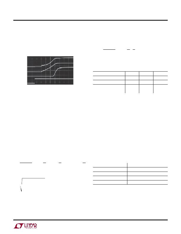
Soft-Start (LT3465)
The LT3465 has an internal soft-start circuit to limit the
inductors, which is usually the case for this application,
the peak inrush current can be simplified as follows:
? exp ? – ? ?
input current during circuit start-up. The circuit start-up
waveforms are shown in Figure 5.
I P =
V IN – 0 . 6
L ? ω
? α π ?
? ω 2 ?
Table 3 gives inrush peak currents for some component
selections.
I IN 50mA/DIV
V OUT 5V/DIV
V FB 100mV/DIV
Table 3. Inrush Peak Current
V IN (V) r ( ? )
5 0.5
L ( μ H)
22
C ( μ F)
0.22
I P (A)
0.38
CTRL 5V/DIV
5
0.5
22
1
0.70
V IN = 3.6V
4 LEDs, 20mA
L = 22 μ H
C = 0.22 μ F
200 μ s/DIV
3465 F05
3.6
5
0.5
0.5
22
33
0.22
1
0.26
0.60
Figure 5. Start-Up Waveforms
Inrush Current
The LT3465 and LT3465A have a built-in Schottky diode.
When supply voltage is applied to the V IN pin, the voltage
difference between V IN and V OUT generates inrush current
flowing from input through the inductor and the Schottky
diode to charge the output capacitor to V IN . The maximum
current the Schottky diode in the LT3465 and LT3465A
can sustain is 1A. The selection of inductor and capacitor
value should ensure the peak of the inrush current to be
below 1A. The peak inrush current can be calculated
as follows:
LED Current and Dimming Control
The LED current is controlled by the feedback resistor (R1
in Figure 1) and the feedback reference voltage.
I LED = V FB /R FB
The CTRL pin controls the feedback reference voltage as
shown in the Typical Performance Characteristics. For
CTRL higher than 1.8V, the feedback reference is 200mV,
which results in full LED current. CTRL pin can be used as
dimming control when CTRL voltage is between 200mV to
1.5V. In order to have accurate LED current, precision
resistors are preferred (1% is recommended). The for-
mula and table for R FB selection are shown below.
R FB = 200mV/I LED-Full (1)
? ? ω
? α ? ? ?
? α ? ? ?
? exp ? – ? arctan ? ? ? ? sin ? arctan ? ? ?
( )
r + 1 . 5
I P =
α =
ω =
V IN – 0 . 6
L ? ω
r + 1 . 5
2 ? L
1
–
L ? C
4 ? L 2
2
? ?
? α ? ω ? ? ? ? ω ? ?
Table 4. R FB Resistor Value Selection
FULL I LED (mA) R1 ( ? )
5 40.0
10 20.0
15 13.3
20 10.0
The filtered PWM signal can be considered to be an
adjustable DC voltage. It can be used to adjust the CTRL
where L is the inductance, r is the resistance of the
inductor and C is the output capacitance. For low DCR
voltage source in dimming control. The circuit is shown in
Figure 6. The corner frequency of R1 and C1 should be
3465afa
9
发布紧急采购,3分钟左右您将得到回复。
相关PDF资料
LT3466EDD-1#PBF
IC LED DRIVR WHITE BCKLGT 10-DFN
LT3466EDD#PBF
IC LED DRIVR WHITE BCKLGT 10-DFN
LT3474IFE#PBF
IC LED DRVR HP CONS CURR 16TSSOP
LT3475EFE-1#PBF
IC LED DRVR HP CONS CURR 20TSSOP
LT3476EUHF#PBF
IC LED DRVR HP CONST CURR 38-QFN
LT3477EFE#PBF
IC LED DRVR HP CONS CURR 20TSSOP
LT3478IFE#PBF
IC LED DRVR HP CONS CURR 16TSSOP
LT3486EFE#PBF
IC LED DRVR WHITE BCKLGT 16TSSOP
相关代理商/技术参数
LT3465AES6#TRPBF
功能描述:IC LED DRIVR WHITE BCKLGT TSOT-6 RoHS:是 类别:集成电路 (IC) >> PMIC - LED 驱动器 系列:- 标准包装:6,000 系列:- 恒定电流:- 恒定电压:- 拓扑:开路漏极,PWM 输出数:4 内部驱动器:是 类型 - 主要:LED 闪烁器 类型 - 次要:- 频率:400kHz 电源电压:2.3 V ~ 5.5 V 输出电压:- 安装类型:表面贴装 封装/外壳:8-VFDFN 裸露焊盘 供应商设备封装:8-HVSON 包装:带卷 (TR) 工作温度:-40°C ~ 85°C 其它名称:935286881118PCA9553TK/02-TPCA9553TK/02-T-ND
LT3465AES6TRMPBF
制造商:Linear Technology 功能描述:LED Driver 6-Seg 3.3/5/9/12/15V TSOT23-6
LT3465ES6
制造商:Linear Technology 功能描述:LED DRVR 6Segment 3.3V/5V/9V/12V/15V 6-Pin TSOT-23
LT3465ES6#PBF
制造商:Linear Technology 功能描述:IC WHITE LED DRIVER SCHOTTKY SMD 制造商:Linear Technology 功能描述:IC, WHITE LED DRIVER, SCHOTTKY, SMD 制造商:Linear Technology 功能描述:LED DRIVER, BOOST, PWM/ANALOGUE, 2.4MHZ, TSOT-23-6; Topology:Boost (Step Up); No. of Outputs:1; Output Voltage:30V; Driver Case Style:TSOT-23; Input Voltage Min:2.7V; Input Voltage Max:16V; Dimming Control Type:PWM / Analogue ;RoHS Compliant: Yes
LT3465ES6#TR
功能描述:IC LED DRIVR WHITE BCKLGT TSOT-6 RoHS:否 类别:集成电路 (IC) >> PMIC - LED 驱动器 系列:- 标准包装:6,000 系列:- 恒定电流:- 恒定电压:- 拓扑:开路漏极,PWM 输出数:4 内部驱动器:是 类型 - 主要:LED 闪烁器 类型 - 次要:- 频率:400kHz 电源电压:2.3 V ~ 5.5 V 输出电压:- 安装类型:表面贴装 封装/外壳:8-VFDFN 裸露焊盘 供应商设备封装:8-HVSON 包装:带卷 (TR) 工作温度:-40°C ~ 85°C 其它名称:935286881118PCA9553TK/02-TPCA9553TK/02-T-ND
LT3465ES6#TRM
功能描述:IC LED DRIVR WHITE BCKLGT TSOT-6 RoHS:否 类别:集成电路 (IC) >> PMIC - LED 驱动器 系列:- 标准包装:6,000 系列:- 恒定电流:- 恒定电压:- 拓扑:开路漏极,PWM 输出数:4 内部驱动器:是 类型 - 主要:LED 闪烁器 类型 - 次要:- 频率:400kHz 电源电压:2.3 V ~ 5.5 V 输出电压:- 安装类型:表面贴装 封装/外壳:8-VFDFN 裸露焊盘 供应商设备封装:8-HVSON 包装:带卷 (TR) 工作温度:-40°C ~ 85°C 其它名称:935286881118PCA9553TK/02-TPCA9553TK/02-T-ND
LT3465ES6#TRMPBF
功能描述:IC LED DRIVR WHITE BCKLGT TSOT-6 RoHS:是 类别:集成电路 (IC) >> PMIC - LED 驱动器 系列:- 标准包装:60 系列:- 恒定电流:- 恒定电压:- 拓扑:线性(LDO),PWM,升压(升压) 输出数:8 内部驱动器:是 类型 - 主要:背光 类型 - 次要:RGB,白色 LED 频率:500kHz ~ 1.5MHz 电源电压:4.75 V ~ 26 V 输出电压:45V 安装类型:* 封装/外壳:* 供应商设备封装:* 包装:* 工作温度:-40°C ~ 85°C
LT3465ES6#TRMPBF
制造商:Linear Technology 功能描述:DC/DC Converter IC
